Let me tell you a bit about the ESP8266.
The ESP8266 is a 32-bit micro from Espressif, which is a manufacturer based in China. It’s grabbed the attention of the Internet-of-Things (IoT) crowd because it’s a complete WiFi-enabled chip for like $3. Which is incredible.
Furthering the incrediblation (which is a perfectly cromulent word) is the fact that there is an Arduino plugin that lets you use the Arduino IDE to program the ESP8266.
So let’s look at a project I did over the weekend and see what levels of incrediblation are available with this chip.
Fundamentals
The ESP8266EX is the micro itself, and it’s available in about a dozen and a half carrier boards designated ESP-01 through ESP-131. Each has its own feature set, available pins, and FCC certification (sometimes).
The modules generally have some kind of flash-based memory that you can program or boot from, and the micro allows for three different booting strategies2:
| MTD0 | GPIO0 | GPIO2 | Mode | Description |
|---|---|---|---|---|
| Low | Low | High | UART | Download code from UART |
| Low | High | High | SPI | Boot from SPI flash |
| High | X | X | SDIO | Boot from SD card |
Note: MTD0 is the same as GPIO15
This table indicates that if you want to upload new firmware you’re going to need to set GPIO15 and GPIO0 low, and bring GPIO2 high before powering on the micro. Having said that, both Adafruit and SparkFun offer ESP8266-based boards that you don’t have to fiddle with to program. I’ve had decent luck with the one from Adafruit but read that the one from Sparkfun can be finicky.
Setting up Arduino IDE
Now that we have an idea of how to flash the board, let’s set up a development environment.
Download the latest version of the Arduino IDE (I’m looking at 1.6.6) and install. You’ll then want to follow the instructions on the Arduino ESP8266 project page that indicate how to install the ESP8266 add-on.
At this point if you’re using the Adafruit ESP8266 development board you can load up the Blink example (File - Examples - 01.Basics - Blink) and upload that image to the board. You’ll see the onboard LED blink each second. You won’t have to boot into SPI flash mode; the Arduino will soft-reset the board and execute the program after uploading.
Creating a Temperature-serving Web Server Thingie
For this project you’ll need the Adafruit dev board previously mentioned as well as a DS18B20 temperature sensor, also available from Adafruit.
First you’ll want to wire it up similarly to this diagram:
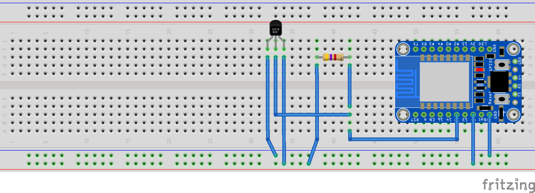
Sorry for the super-wide breadboard! I’m far too lazy to find a smaller one. Also the board from Adafruit might look different than the one in the diagram. That’s okay, just make sure you’re connecting Vcc to Vcc, Gnd to Gnd, and GPIO12 is the data line.
Next, let’s look at some source code!
#include <ESP8266WiFi.h>
#include <ESP8266WebServer.h>
#include <OneWire.h>
#include <DallasTemperature.h>

#define ONE_WIRE_BUS 12 // see? i told you gpio12 was the data line

const char* ssid = "Your SSID here";
const char* password = "Your password here";

ESP8266WebServer server(80);
OneWire oneWire(ONE_WIRE_BUS);
DallasTemperature sensors(&oneWire);

void setup() {
  Serial.begin(115200);
  sensors.begin();
  WiFi.begin(ssid, password);
  while (WiFi.status() != WL_CONNECTED)
    {
      delay(1000);
      Serial.print(".");
    }

  Serial.println("");
  Serial.println("WiFi connected");
  Serial.println("IP address: ");
  Serial.println(WiFi.localIP());

  server.on("/", []()
  {
    sensors.requestTemperatures();
    server.send(200, "text/html", String(sensors.getTempFByIndex(0)));
  });

  server.begin();
}

void loop()
{
  server.handleClient();
}
Upload that source code to the micro and turn on the Serial Monitor (under the ‘Tools’ menu) and you should see something like the following:
....
WiFi connected
IP address:
192.168.1.119
Fire up your web browser, visit the IP you saw in the Serial Monitor and VOILA (that’s French for “look, a temperature!”).
If you’re having trouble uploading and you’re using the Adafruit module, take a look at these instructions.
So what can I do with this?
I have some different software posting my data directly to data.sparkfun.com once a minute. I’m collecting data on different rooms in my house to check out furnace efficiency. Hopefully I’ll be able to tune my programmable thermostat to save myself some money this winter.
You can view the results at analog.io, although it’s not a very intuitive site. You have to check the ‘temp’ box on the left and then click the ‘load all’ button in the upper right of the graph. Once the data comes up you can totally see trends like how often my furnace kicks on and off (look at those spikes every 40 minutes or so) and when I’m physically in the room (the average temperature goes up about a degree).
COOL STUFF.
Anything else?
Plenty! Here are some ideas for future blog posts:
- How to flash the Espressif-supplied AT firmware (and what does that sentence mean)
- Using Espressif’s SDK to write your own firmware
- Low-powered nonsense (you can sleep the micro at its consumption drops to 60uA!)
- Something else? Leave a comment!
All in all it’s been a lot of fun using this micro. I highly recommend taking a few days and fiddling with it.
It’s a small chip but it packs a lot of incrediblation.
-
There are some boards with letters as well, for example the ESP-12E. For a complete list see the Wikipedia page ↩
-
This table was shamelessly stolen from an ESP8266 wiki ↩